
“Space rockets carrying automatic scientific stations with various instruments aboard rapidly set off toward the nearest planets of the solar system.
Of these, Mars and Venus are of the greatest interest…” — these are words from an article by S. P. Korolev published in Pravda on November 10, 1960. At that time, three months remained before the launch of “Venera-1.”
At the design bureau headed by S. P. Korolev, work was in full swing on the design of the automatic interplanetary station “Venera-1” and the upper (boost) stage of the launch vehicle, which was to place it onto the flight path toward the Morning Star. Development of the station had begun several months earlier, when it became clear to the designers that the capabilities of the launch vehicle made it possible to additionally install a boost stage that would place the spacecraft into Earth orbit together with the space vehicle and then, from there, start it on a trajectory toward other planets.
The creators of the automatic interplanetary station (AIS) took into account all the experience accumulated by that time in developing the first artificial Earth satellites and the first lunar spacecraft. At the same time, much about this station was genuinely new.
Thus, for the first time an AIS was equipped with a corrective propulsion system designed by Chief Designer A. M. Isaev for trajectory correction. Without such correction, flights to the planets of the solar system are impossible.
For the first time, a multi-mode orientation and motion-control system for the station was developed. With its help, it was possible for many months to maintain a constant orientation of the plane of the solar panel arrays toward the Sun, periodically point the onboard parabolic antenna toward Earth, and perform precise (to within single angular minutes) orientation of the station relative to the stars. This same system stabilized the station in space during operation of the corrective engine. It included complex optical instruments capable of “seeing” not only the bright Sun, but also the Earth from distances of hundreds of millions of kilometers, when it appears as a tiny star.
A highly directional parabolic antenna (2 m in diameter) made it possible to maintain ultra-long-distance space radio communication with Earth in the centimeter wavelength range. In total, three radio-telemetry systems operated onboard the station for different bands—meter, decimeter, and centimeter.
The “Venera-1” station also used the same thermal control system as on “Luna-3.” The temperature inside the compartment was regulated by rotating louvers installed on the cylindrical part of the sealed корпус.
During the flight, measurements were carried out of cosmic rays, magnetic fields, charged particles of interplanetary gas and corpuscular flows from the Sun, as well as the registration of micrometeors.
To place “Venera-1” onto an interplanetary trajectory, it was necessary to create a new stage. The mass of the station was 643.5 kg. Perhaps the creation of this stage can be called one of the most important and remarkable achievements of the new space experiment. After all, the rocket’s propulsion system had to be started in weightlessness (after a relatively long stay in the harsh conditions of space). To develop such a system at that time meant making a qualitatively new step in the development of rocket and space technology. The designers had to solve many problems. The rocket control system had to ensure the required orientation during orbital flight around Earth, stabilization of the rocket during engine operation, and ignition at the calculated time. In addition, it was necessary to regulate the thermal conditions of the fuel tanks containing oxygen. Finally, it was necessary to create a fuel feed system to the combustion chamber that would allow the engine to be started quickly. For this purpose, solid-propellant motors were installed on the space rocket, imparting a short-term acceleration sufficient for the liquid fuel, which was in a weightless state, to begin flowing into the combustion chamber.
Careful calculations, fundamentally new design solutions, and experimental testing on Earth under conditions close to those of space flight—this was the result of all this work: a new automatic interplanetary station and rocket stage were born. For the first time, a vehicle of this type started from an artificial Earth satellite orbit on February 12, 1961. Subsequently, the space rocket placed automatic spacecraft of the “Luna,” “Mars,” “Venera,” and “Zond” types onto interplanetary trajectories. With its help, “Molniya” communications satellites were launched into highly elliptical orbits. Communication with the station was maintained at distances of up to 5 million km. Even from there, from the depths of the solar system, the necessary scientific information was transmitted to Earth.
Today, when interplanetary spacecraft are sent unimaginably far from Earth, this result seems very modest. But then, in 1961, such a distance seemed fantastic—after all, radio waves had to traverse outer space saturated with various particles and all kinds of electromagnetic radiation, the nature of which was still poorly understood at that time.
So what were the results of the “Venera-1” flight? First, scientists obtained the first data from scientific measurements at a considerable distance from Earth, in the region of space known as deep space. Second, the developers of rocket and space technology were enriched with new material, since very much on this station was tested for the first time.
The flight confirmed the correctness of the chosen directions. The creation and launch of the automatic interplanetary station “Venera-1” was an important stage in the development of rocket and space technology, one of the bright pages in the history of domestic cosmonautics.
MARINA MARCHENKO, engineer
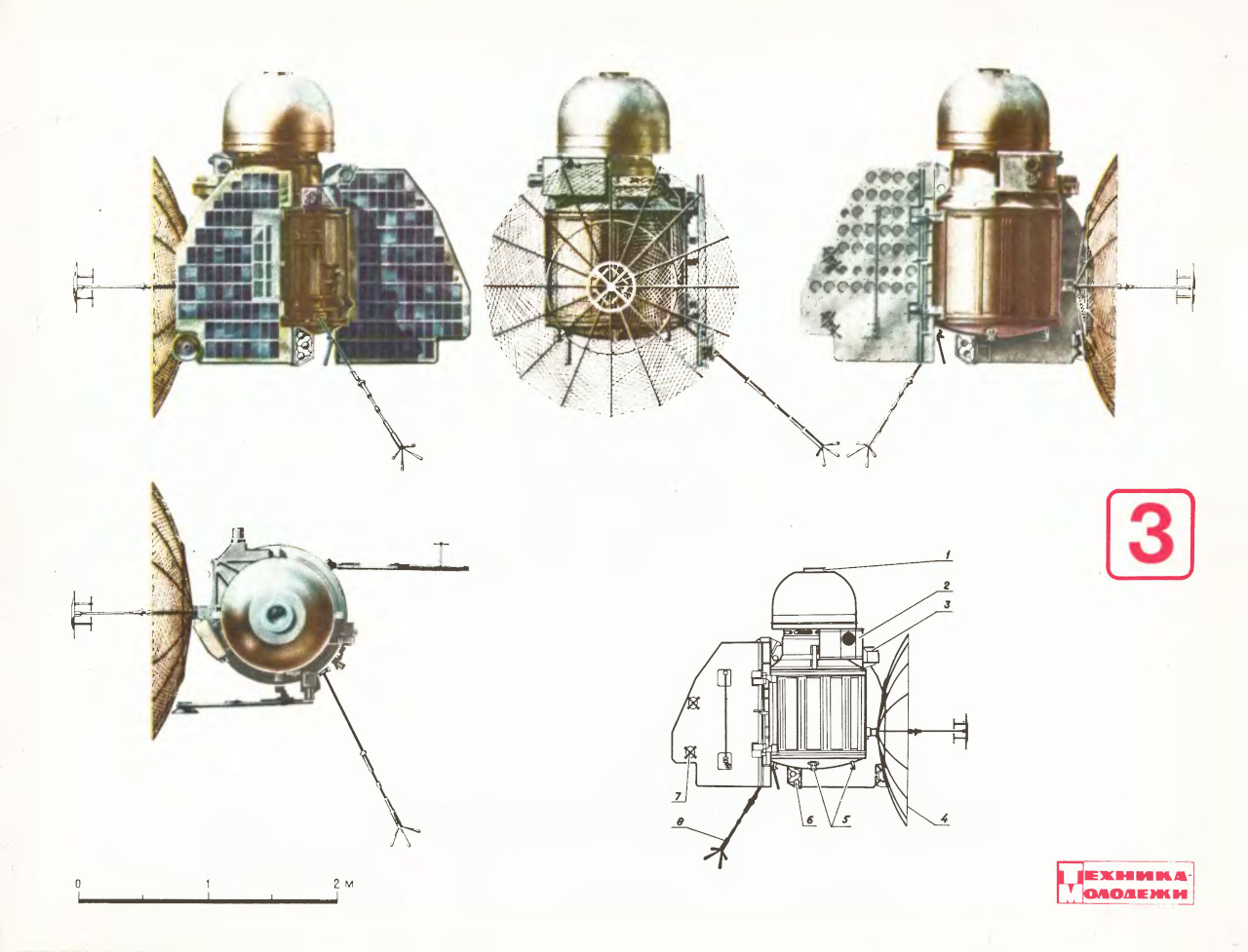 The drawing shows the automatic interplanetary station “Venera-1” in three projections. The diagram shows its structure. The numbers indicate:
1 — nozzle of the corrective propulsion system;
2 — sensor for precise orientation toward the Sun and stars;
3 — sensor for orientation toward Earth;
4 — parabolic antenna;
5 — control nozzles of the orientation system;
6 — thermal sensors;
7 — low-directional antenna;
8 — whip antenna.